EVPN and VRFs: The Security Architecture Your Data Center Actually Needs
How EVPN with VRF isolation extends from the physical fabric to the Windows Hyper-V virtual switch — and why it's a real security upgrade over VLANs.

Part 2 of a series on network isolation in modern data centers — read Part 1: What Are VRFs and How They Work first if VRFs are new to you.
If you’ve been running multi-tenant workloads on traditional VLANs and feeling pretty good about your “isolation,” I’ve got some uncomfortable news. VLANs were designed for traffic management, not security boundaries. They’re the drywall between hotel rooms — technically separating spaces, but one determined guest with a drill changes everything.
EVPN with VRF-based isolation is the concrete wall upgrade. And if you’re running Hyper-V workloads on a spine-leaf fabric, the way this integrates with the Windows Hyper-V virtual switch is genuinely elegant — once you understand the full stack.
I’ve been building these architectures at scale using Cisco Nexus leaf switches with VXLAN/EVPN overlay, Cisco C9336C-FX3 border/spine switches, and Windows Server hosts running Hyper-V with Switch Embedded Teaming (SET). Here’s how it all connects and why it matters for security.
What Are EVPN and VRFs? (The 60-Second Version)
VRF (Virtual Routing and Forwarding) is essentially multiple independent routing tables on the same physical switch. Think of it like running several completely separate routers inside one box. Traffic in VRF-A has zero visibility into VRF-B’s routing table. They don’t know each other exists. It’s not a filter or an ACL — it’s a fundamentally separate forwarding plane.
EVPN (Ethernet VPN) is the control plane that makes VRFs work across your entire fabric. It’s a BGP address family (L2VPN EVPN) that distributes MAC addresses, IP addresses, and VRF membership information between switches. Instead of flooding unknown traffic everywhere like traditional Layer 2, EVPN learns exactly where every endpoint lives and builds precise forwarding entries.
VXLAN is the data plane — the tunnel that carries isolated traffic between switches across a shared IP underlay. Each tenant segment gets a unique VNI (VXLAN Network Identifier), which maps to a VLAN locally on each switch.
Put them together: EVPN tells your fabric where things are and who they belong to. VRFs enforce isolation between tenants. VXLAN carries the traffic. Three layers, one architecture, actual security.
Why VRFs Are a Security Upgrade Over VLANs
Here’s where network engineers sometimes push back: “I already have VLANs separating my tenants. How is this different?”
It’s different in ways that matter when you’re defending against lateral movement:
1. Routing Table Isolation (Not Just L2 Segmentation)
A VLAN is a Layer 2 broadcast domain. A VRF is a Layer 3 routing instance. VLANs share the same routing table — if something goes wrong (misconfigured trunk, VLAN hopping, a rogue device), traffic can leak between segments because the router knows about all of them.
With VRFs, the routing table for tenant A literally doesn’t contain routes for tenant B. You can’t route to what doesn’t exist in your forwarding table. It’s isolation by architecture, not by policy.
2. Control Plane Precision
EVPN uses BGP to distribute MAC/IP bindings with route targets (RTs) that scope advertisements to specific VRFs. When a switch learns a new MAC address in VRF WORKLOAD, it advertises that binding with a route target like 10201:10201. Only switches importing that RT will install the route.
Compare this to traditional flooding: broadcast a frame, every switch in the VLAN sees it, every host in the VLAN processes it. EVPN replaces this with targeted, control-plane-driven forwarding. Less broadcast traffic, less attack surface.
3. No More VRRP Sprawl
Traditional HA gateway designs (VRRP/HSRP) require multiple IPs per VLAN per switch — a virtual IP, plus unique self-IPs on each peer. In a fabric with dozens of VLANs, that’s a lot of exposed IPs, each one a potential target.
EVPN anycast gateway eliminates all of this:
| Traditional VRRP | EVPN Anycast Gateway | |
|---|---|---|
| Gateway | .1 = VRRP VIP (shared) | .1 = Anycast GW (ALL leaves) |
| Self-IPs | .2 = TOR1, .3 = TOR2 (unique per switch) | None needed |
| Protocol overhead | VRRP state, VRIDs, gratuitous ARP | None |
| IPs consumed per VLAN | 3 | 1 |
Every leaf switch in the fabric advertises the same gateway IP and MAC (00:01:01:01:01:01 in our deployment). Hosts always route to the nearest leaf. No VRRP state to attack, no self-IPs to probe, no gratuitous ARP storms during failover.
4. MAC/IP Binding Enforcement
EVPN Type-2 routes bind MAC addresses to IP addresses at the control plane level. The fabric knows that MAC aa:bb:cc:dd:ee:ff belongs to IP 100.78.108.50 on VNI 10201, reachable via VTEP 100.71.93.148. Spoofing becomes significantly harder when the fabric maintains authoritative bindings distributed via BGP.
The Architecture: Spine-Leaf with VXLAN/EVPN
Here’s the physical topology I’m working with — a single-rack deployment with spine-leaf that scales to multi-rack:
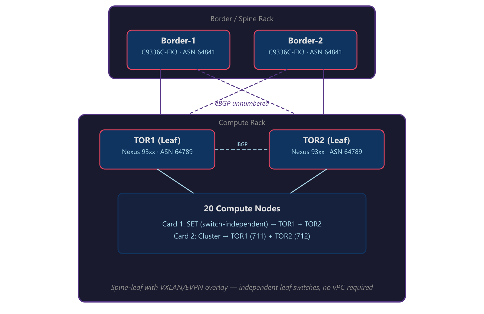
Key design elements:
- eBGP unnumbered between leaves and spines — no IP addresses to manage on fabric links, no numbered /30s to track
- Dual-loopback model — Loopback0 is the shared VTEP IP (
100.71.93.148/32), Loopback1 is the unique BGP router-ID (100.71.93.149/32and.150/32) - Independent leaf switches — each TOR operates as a standalone EVPN leaf. No vPC or MLAG is required because Windows SET is switch-independent (no LACP) and EVPN anycast gateway provides redundant default gateways on every leaf
- EVPN overlay sessions ride loopback-to-loopback (
ebgp-multihop 2) to the border switches for route exchange
VNI-to-VLAN Mapping
Each VLAN maps to a unique VXLAN Network Identifier. Traffic entering a leaf switch on VLAN 201 gets encapsulated with VNI 10201 before traversing the fabric:
| VLAN | VNI | Purpose | Subnet | Anycast GW |
|---|---|---|---|---|
| 7 | 10007 | Infrastructure | 100.68.12.0/24 | 100.68.12.1 |
| 6 | 10006 | Network Virtualization | 100.71.189.0/24 | 100.71.189.1 |
| 201 | 10201 | Accounting | 100.78.108.0/23 | 100.78.108.1 |
| 301 | 10301 | IT Services | 100.78.110.0/23 | 100.78.110.1 |
| 500 | 10500 | Engineering | 100.68.13.0/24 | 100.68.13.1 |
| 600 | 10600 | HR & Operations | 100.64.72.0/23 | 100.64.72.1 |
| 650 | 10650 | Development / QA | 100.76.34.0/25 | 100.76.34.1 |
All tenant-facing VNIs live inside VRF WORKLOAD. Infrastructure and network virtualization VLANs are also in the VRF but serve the fabric itself rather than end-user workloads.
Manual EVI: Explicit Control Over Your Overlay
In production VXLAN/EVPN fabrics, auto-derived EVI settings can sometimes cause unexpected behavior — especially at scale. Manual EVI configuration with explicit Route Distinguishers and Route Targets gives you full control:
1
2
3
4
evpn
  evi 10201
    rd 100.71.93.149:10201
    route-target both 10201:10201
Each EVI maps 1:1 to a VNI. The RD uses the leaf’s unique router-ID (Loopback1) to ensure uniqueness across the fabric. The RT (10201:10201) controls which switches import/export routes for that segment. This is where VRF isolation is actually enforced at the control plane — only switches configured to import RT 10201:10201 will have reachability to that segment.
Where Windows Virtual Switch Enters the Picture
Here’s the part that makes this architecture interesting: the isolation model doesn’t stop at the physical switch. It extends into the host through the Hyper-V Virtual Switch running in Switch Embedded Teaming (SET) mode.
How the Host Connects
Each compute node connects to the fabric with a dual-port NIC:
| Card | Function | Connection | Teaming |
|---|---|---|---|
| Card 1 (OCP) | Compute + Management | Port A → TOR1, Port B → TOR2 (trunk) | Windows SET |
Card 1 is where the magic happens for workload isolation. Both ports connect as independent trunks carrying the management VLAN (native, untagged) plus all tenant VLANs. The Windows SET virtual switch teams these two physical NICs in switch-independent mode — no LACP, no port-channel. Each NIC appears as a standalone port to its respective TOR switch.
The SET Virtual Switch: Bridge Between Physical and Virtual
The Hyper-V virtual switch in SET mode presents a single virtual switch to the OS and VMs while distributing traffic across both physical NICs using a hash-based algorithm (Hyper-V Port mode). Each VM’s MAC address is pinned to one physical NIC for inbound traffic, while different VMs can be spread across different NICs. This is switch-independent — the TOR switches have no knowledge that these NICs are teamed. If TOR1 goes down, SET detects the link failure and remaps all affected MAC addresses to the surviving NIC connected to TOR2.
But here’s the security-relevant part: the virtual switch enforces VLAN isolation through access port assignments. When you configure a VM’s virtual NIC on the vSwitch, you assign it to a specific VLAN as an access port — the VM sees a flat, untagged connection and has no awareness of VLANs. The vSwitch handles the 802.1Q tagging before traffic hits the physical NIC, and the TOR switch only allows VLANs explicitly configured in the trunk allowed list.
The isolation chain looks like this:
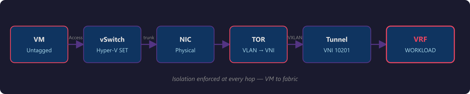
At every hop, the traffic is constrained:
- Virtual switch — each VM connects as an access port; the vSwitch assigns the VLAN and handles tagging
- Physical NIC — SET team member carries only allowed VLANs (switch-independent, no LACP)
- TOR switch port — trunk allowed list restricts to the configured tenant VLANs
- VXLAN encapsulation — maps to specific VNI
- VRF — routing table isolation in the fabric
- EVPN RT — control plane scoping of route advertisements
A VM on the Accounting VLAN (201) can’t reach IT Services (VLAN 301) resources unless the VRF is explicitly configured to route between those VNIs. And even then, you can apply route-map policies at the VRF level for granular control.
What This Means for Multi-Tenant Security
When you combine EVPN/VRF on the physical fabric with Windows virtual switch enforcement, you get defense in depth that traditional VLAN designs simply can’t match:
1. No single point of policy enforcement. Isolation is enforced at the VM, the virtual switch, the physical switch port, the VXLAN encapsulation, and the VRF. Compromising one layer doesn’t compromise the others.
2. Control plane integrity. EVPN distributes MAC/IP bindings via BGP with authenticated session establishment (MD5 or TCP-AO). Route targets ensure advertisements stay within their VRF scope. This isn’t broadcast-based discovery — it’s deterministic, verifiable forwarding.
3. Reduced blast radius. In a VLAN-only design, a compromised host in VLAN 201 can ARP scan the entire broadcast domain. With EVPN, the switch only has forwarding entries for endpoints it learned via BGP. Unknown unicast flooding is suppressed by default — the fabric won’t forward traffic to destinations it hasn’t learned.
4. Scalable isolation. VLANs cap out at 4094. VNIs go to 16 million. VRFs scale with your routing table capacity. When you need to add a new tenant, it’s a VNI mapping and an RT import — not a prayer that your VLAN ID space hasn’t been exhausted.
5. Consistent policy from edge to edge. The same VRF that isolates traffic on the leaf switch is the same VRF context applied in the spine. The anycast gateway means every leaf looks identical to hosts. There’s no asymmetry in the forwarding path to exploit.
Practical Takeaways for Network Engineers
If you’re designing multi-tenant environments on any VXLAN/EVPN fabric with Hyper-V hosts, here’s what I’d prioritize:
Start with VRF design, not VLAN design. Think about your isolation domains first. Which workloads need to talk to each other? Which absolutely must not? Map VRFs to business requirements, then map VNIs and VLANs to VRFs.
Use anycast gateway everywhere. If you’re still running VRRP or HSRP on your leaf switches, you’re carrying unnecessary complexity and attack surface. Anycast gateway is simpler, faster (no failover delay), and more secure (no self-IPs to probe).
Manual EVI for large or multi-vendor fabrics. Don’t rely on auto-EVI in production. Explicit RD/RT configuration is more work upfront but eliminates surprises at scale.
Don’t forget the host layer. The best fabric security means nothing if the virtual switch is misconfigured. Ensure trunk allowed lists match between the physical switch and the SET virtual switch config. Audit vSwitch port assignments against your VRF design.
Audit vSwitch port assignments regularly. As tenants come and go, stale access port VLAN assignments on the vSwitch can create unexpected reachability. Periodic audits of your VNI-to-VLAN-to-VRF mapping keep the isolation model honest.
Document your VNI-to-VLAN-to-VRF mapping. This is your source of truth. When something breaks at 2 AM, you need to trace from a VM’s vSwitch port assignment through the VLAN, VNI, and VRF to the route target. Make that path obvious.
Wrapping Up
EVPN with VRF isolation isn’t just a networking upgrade — it’s a security architecture. When you pair it with the Windows Hyper-V virtual switch in SET mode, you get isolation that runs from the VM all the way through the physical fabric, enforced at every layer.
Traditional VLANs gave us segmentation. EVPN/VRF gives us isolation. There’s a meaningful difference, and if you’re running multi-tenant workloads on Hyper-V clusters, that difference is worth the migration effort.
The best part? Once the fabric is built, adding new tenants is clean and repeatable — a VNI mapping, an EVI, a route target, and a VLAN on the virtual switch. No VRRP groups to configure, no IP addresses to allocate per switch, no broadcast domains to worry about flooding.
Build the foundation right, and the rest is configuration management.
This is Part 2 of a series on network isolation. Read Part 1: What Are VRFs and How They Work if you haven’t already.
This post is based on production architecture work with single-rack and multi-rack data center deployments. The configurations shown use Cisco NX-OS on Nexus leaf and spine switches. Your mileage may vary with different vendors, but the EVPN/VRF principles are universal.