What Are VRFs and How They Work
A practical, no-nonsense guide to Virtual Routing and Forwarding (VRF) for engineers who know networking but haven't clicked with VRFs yet.

Part 1 of a series on network isolation in modern data centers
You know that moment when someone at work casually drops “yeah, just put it in a VRF” and half the room nods while the other half quietly dies inside?
I’ve been there. I’ve been the person nodding while furiously Googling under the table. And I’ve been on the other side too — explaining VRFs to sharp engineers who can subnet in their sleep but can’t quite articulate why a VRF isn’t just “a fancy VLAN.”
So let’s fix that. No vendor slides. No RFC citations. Just a real explanation of what VRFs are, why they exist, and how they actually work — with examples from production data center deployments I’ve built.
The Problem: One Router, Too Many Opinions
Here’s the scenario that invented VRFs:
You have a single physical router. It has one routing table. Every interface, every connected subnet, every learned route — it all goes into one big table. Traffic from any interface can, in theory, reach any other interface.
Now imagine you’re running infrastructure for multiple tenants. Tenant A uses 10.0.1.0/24. Tenant B also uses 10.0.1.0/24. Because of course they do. Everyone loves RFC 1918.
With a single routing table, this is a disaster. The router sees two identical prefixes and has no idea which is which. Worse — even if the subnets were different, you’ve got zero isolation. Tenant A’s traffic can find its way to Tenant B’s network if a route exists.
You could buy separate physical routers for each tenant. That works, but now you’ve got a rack full of hardware doing what one box should handle.
VRFs solve this. They let you run multiple independent routing tables inside a single router. Each VRF is its own isolated universe.
The Mental Model: An Apartment Building
Think of a physical router (or switch) as an apartment building.
Without VRFs, it’s a warehouse — one giant open floor plan. Everyone’s stuff is in one room. Your mail gets mixed with your neighbor’s. Someone else’s plumbing problem becomes your plumbing problem.
A VRF is an apartment. Same building, same physical structure, but each unit has:
- Its own address (separate routing table)
- Its own mailbox (interfaces assigned to the VRF)
- Its own plumbing and electrical (forwarding path)
- Walls between units (isolation — traffic can’t leak between VRFs)
The key insight: VRFs are virtual routers living inside a physical one. Each VRF has its own routing table, its own forwarding decisions, and its own view of the network. An interface assigned to VRF “Blue” has absolutely no idea that VRF “Red” exists on the same box.
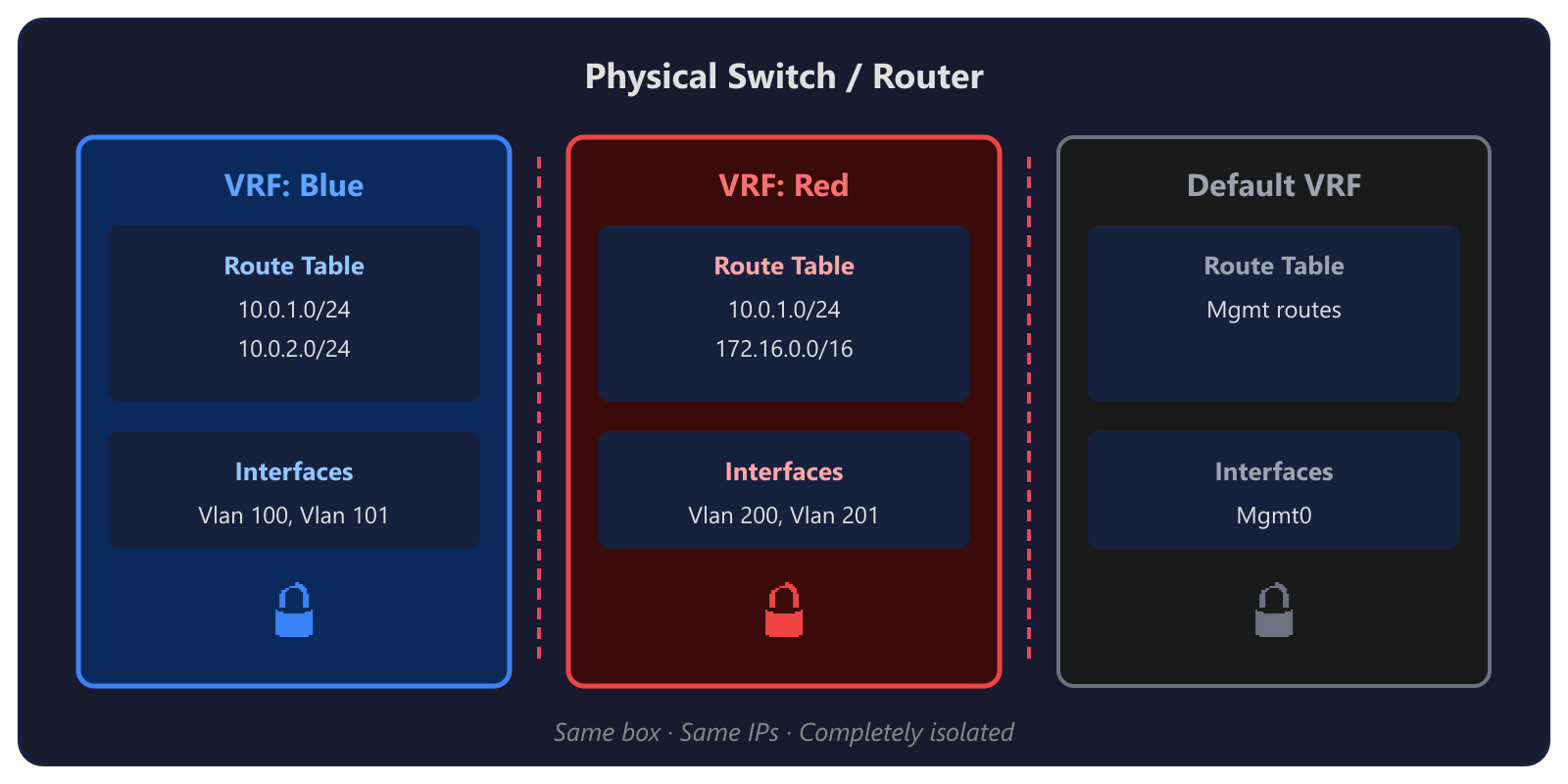 Same box · Same IPs · Completely isolated
Notice that both VRFs have 10.0.1.0/24? No problem. Each routing table is independent. No collisions, no confusion.
How VRFs Actually Work
Okay, analogies are nice. Let’s get technical.
1. Each VRF Gets Its Own Routing Table
This is the core of everything. When you create a VRF, the router carves out a completely separate RIB (Routing Information Base) and FIB (Forwarding Information Base) for it.
Routes learned on interfaces in VRF “A” go into VRF A’s table. Routes in VRF “B” go into B’s table. They never mix unless you explicitly make them (we’ll get to that).
2. Interfaces Are Assigned to a VRF
An interface belongs to exactly one VRF (or the global/default table). When you assign an interface to a VRF, any IP addressing and routing on that interface lives inside that VRF’s world.
! Cisco NX-OS example
vrf context WORKLOAD
!
interface Vlan7
  vrf member WORKLOAD
  ip address 100.68.12.1/24
  no shutdown
That vrf member WORKLOAD line is doing the heavy lifting. It says: “This interface’s routes, ARP entries, and forwarding decisions all happen inside the WORKLOAD VRF. Not the global table. Not any other VRF.”
3. Packets Stay in Their Lane
When a packet arrives on an interface in VRF “WORKLOAD,” the router looks up the destination in WORKLOAD’s routing table only. Not the global table. Not another VRF’s table. If the destination isn’t in WORKLOAD’s table, the packet gets dropped — even if a perfectly valid route exists in another VRF.
This is the isolation guarantee. VRFs are ships passing in the night.
4. Route Distinguishers and Route Targets (RD/RT)
If you’re running VRFs with BGP (especially in MPLS or EVPN environments), you’ll encounter two concepts:
Route Distinguisher (RD): A tag prepended to a route to make it globally unique within BGP. If two VRFs both have
10.0.1.0/24, the RD turns them into64789:1:10.0.1.0/24and64789:2:10.0.1.0/24. The RD doesn’t affect forwarding — it’s bookkeeping so BGP can carry overlapping prefixes without confusion.Route Target (RT): Controls which VRFs import and export routes. When VRF A exports with RT
100:1, any VRF configured to import RT100:1will pull those routes in. This is how you can selectively share routes between VRFs when you actually want them to talk.
Think of it this way: RD = unique mailing address. RT = mailing list subscription. The RD makes sure every route has a unique identity. The RT decides who gets a copy.
VRFs vs. VLANs: The Question Everyone Asks
This is where most of the confusion lives, so let’s kill it:
| VLAN | VRF | |
|---|---|---|
| Layer | Layer 2 (Ethernet frames) | Layer 3 (IP routing) |
| What it isolates | Broadcast domains | Routing tables |
| Scope | A switch or trunk | A router’s routing table |
| Overlapping IPs? | Doesn’t help — VLANs don’t route | Yes — each VRF has its own table |
| Think of it as | Separate Ethernet segments | Separate virtual routers |
VLANs chop up a Layer 2 network into isolated broadcast domains. Hosts in VLAN 10 can’t see Layer 2 traffic from VLAN 20. But the moment you route between them (with an SVI or a router), traffic can cross over.
VRFs chop up the Layer 3 routing plane. Even if two VLANs are routable, sticking them in different VRFs means their traffic never crosses paths at the routing layer.
In practice, you usually use both. VLANs handle L2 segmentation. VRFs handle L3 isolation. They’re complementary, not competing.
Here’s a concrete example: In a multi-tenant data center deployment, you might have VLAN 7 (Infrastructure), VLAN 6 (Network Virtualization), and VLAN 201 (Tenant) — all living inside the WORKLOAD VRF. They can route to each other through that VRF. But VLAN 711 (Cluster management) sits in the global routing table, completely separated from the tenant workloads.
The VLANs give you L2 separation between traffic types. The VRF gives you a hard L3 wall between “tenant stuff” and “infrastructure stuff.”
VRFs in the Real World: Data Center Spine-Leaf
Enough theory. Here’s how this actually looks in production.
In multi-tenant data center deployments, the TOR (Top of Rack) switches use VRFs to isolate tenant and workload traffic from infrastructure management. Here’s a real config from a Cisco Nexus switch:
! VRF for workload/tenant traffic
vrf context WORKLOAD
!
! Each workload VLAN gets assigned to the VRF
interface Vlan7
  description Infrastructure
  vrf member WORKLOAD
  ip address 100.68.12.1/24
  fabric forwarding mode anycast-gateway
!
interface Vlan6
  description Network Virtualization
  vrf member WORKLOAD
  ip address 100.71.189.1/24
  fabric forwarding mode anycast-gateway
!
interface Vlan201
  description Tenant
  vrf member WORKLOAD
  ip address 100.78.108.1/23
  fabric forwarding mode anycast-gateway
!
! Meanwhile, Cluster management stays in the default VRF
interface Vlan711
  description Cluster
  ip address 10.71.1.1/24
  fabric forwarding mode anycast-gateway
See the pattern?
- WORKLOAD VRF: All the tenant and workload traffic — infra, network virtualization, tenant networks, public VIPs, GRE tunnels. These all need to route to each other but must be isolated from the management plane.
- Default VRF: Cluster management, switch management, BMC access. The stuff that runs the infrastructure itself.
This separation is critical. If a misconfigured tenant VM starts spewing traffic, it’s contained within the WORKLOAD VRF. It can’t touch cluster management. It can’t reach the switch management interface. The VRF is the blast wall.
In multi-rack deployments with EVPN/VXLAN, this gets even more powerful — the VRF extends across racks through VXLAN tunnels, giving you consistent L3 isolation across the entire fabric.
Common Misconceptions
Let me save you some future arguments:
“Isn’t a VRF just a VLAN?”
No. VLANs are Layer 2. VRFs are Layer 3. You can have multiple VLANs inside one VRF. You can have the same VLAN number in different VRFs. They operate at completely different layers. (See the table above.)
“Can VRFs talk to each other?”
Not by default — that’s the whole point. But yes, you can enable route leaking to selectively share routes between VRFs. This is sometimes necessary (e.g., a shared services VRF that multiple tenants need to reach). But it’s an explicit, deliberate configuration. VRFs default to total isolation.
“Do I always need VRFs?”
No. If you have a single tenant, a simple network, and no overlapping IP requirements, the global routing table is fine. VRFs add complexity. Use them when you need isolation or overlapping address spaces, not just because they sound cool.
“VRFs slow things down, right?”
Not really. Modern ASICs handle VRF lookups in hardware at line rate. The performance cost is effectively zero on any decent switch or router built in the last decade. The cost is operational complexity, not performance.
“VRF Lite vs. full VRF — what’s the difference?”
VRF Lite is VRFs without MPLS. You get separate routing tables and interface isolation, but you don’t get the MPLS label-switched forwarding. In most modern data center deployments (like ours with EVPN/VXLAN), you’re using VRF Lite with VXLAN as the transport instead of MPLS. Same isolation, different underlay.
Quick Config Example
Here’s a minimal VRF setup on a Cisco Nexus switch. No EVPN, no VXLAN — just raw VRF isolation:
! Step 1: Create the VRF
vrf context TENANT-A
!
! Step 2: Create a VLAN
vlan 100
  name Tenant-A-Servers
!
! Step 3: Create the SVI and assign to the VRF
interface Vlan100
  vrf member TENANT-A
  ip address 10.0.1.1/24
  no shutdown
!
! Step 4: Assign physical ports to the VLAN
interface Ethernet1/1
  switchport mode access
  switchport access vlan 100
  no shutdown
!
! Step 5: Verify
! show ip route vrf TENANT-A
! show ip interface vrf TENANT-A
That’s it. Five steps. Any traffic on VLAN 100 now routes exclusively through TENANT-A’s routing table. It cannot reach the global table or any other VRF.
Want to add BGP for the VRF?
router bgp 64789
  !
  address-family ipv4 unicast vrf TENANT-A
    redistribute connected
  !
Now your VRF’s connected routes are being advertised via BGP — but only within the TENANT-A VRF context.
TL;DR
- VRFs = virtual routers inside one physical box. Separate routing tables, separate forwarding, total isolation.
- VLANs are L2, VRFs are L3. They complement each other. Use both.
- VRFs prevent route leaking between tenants, between management and workload, between anything you want to keep apart.
- Real-world use: Multi-tenant data center deployments use VRFs to isolate tenant/workload traffic from cluster management.
- They’re not scary. A basic VRF config is five lines.
Up Next
Part 2: EVPN, VRFs, and the Windows Virtual Switch — How VRF isolation extends across a multi-rack VXLAN fabric and what happens when the Windows virtual switch enters the picture. We’ll dig into how EVPN carries VRF routes across the data center and where the security boundaries actually live. Coming soon.
Have questions or war stories about VRFs? Find me on GitHub.